Restoring a 1933 Laurehk Musique Model 4 Radio Receiver
Table of Contents
In the era of the Covid-19 pandemic, I started buying ancient radios on Ebay to repair. First I bought a nice 1939 Bakelite AA5 radio with Art Deco styling, which I had wanted to do for a long time. Then I started looking around for something older and stranger, and found this rounded tombstone set from 1933, a "Musique Model 4" from Laurehk Radio Mfg. Co. in Wayne, Michigan, USA. I never knew there were so many radio manufacturers in the early days (hundreds in the United States alone) and Laurekh seems to be about as obscure as they come, a far cry from Philco or RCA. I failed to find any documentation about this line of radios beyond a sparse entry in www.radiomuseum.org. In particular, I could discover no schematic for the Musique Model 4 on the Web. I decided to document the radio as carefully as I could during restoration and to create my own schematic.
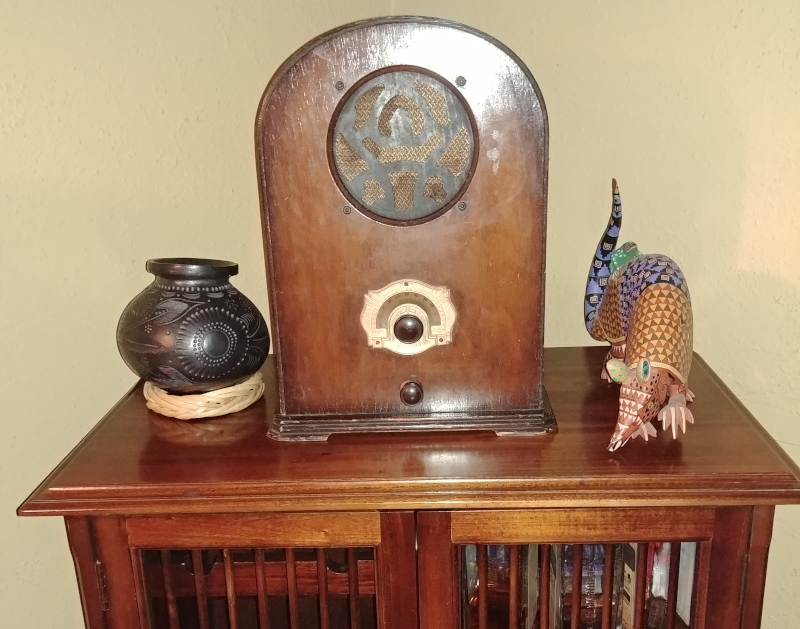
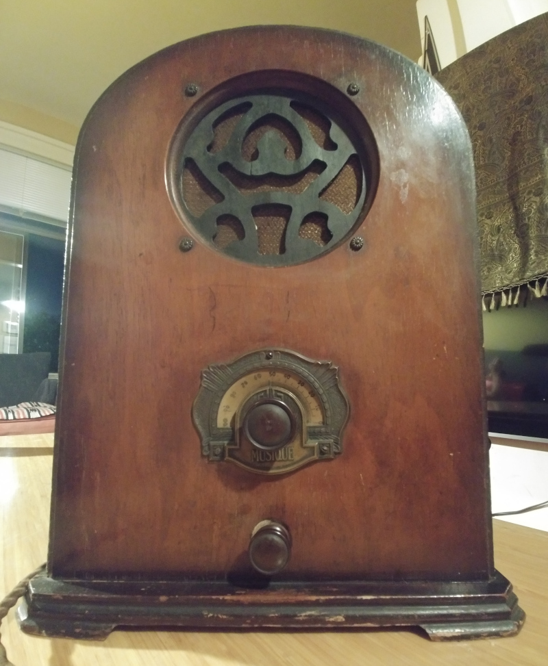
The cabinet is plain but elegant. I had no particular taste for the more elaborate cathedral radios of the period, and the simplicity of this one appealed to me. Besides, cathedrals are more expensive and I was mainly interested in the electronics. I decided there was no need to refinish the cabinet at the moment.
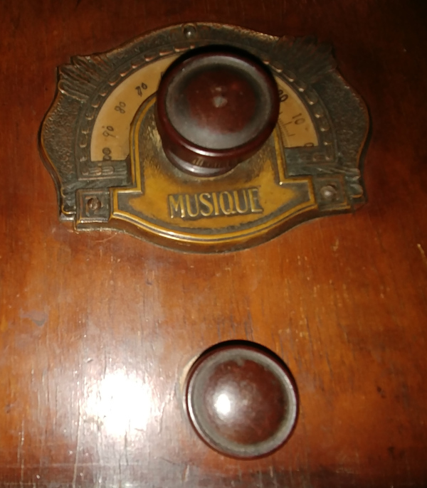
The Bakelite knobs are held in place with headless set screws. The faceplate is brass, heavily tarnished as it came to me. I shined it up, though probably I should have left it alone. The tuner scale is simple linear 1-100, printed on a crescent of translucent celluloid. (The actual frequency range is the standard North American AM broadcast band, 525–1606.5 kHz.) The indicator seems to have worn away the numbers on the left, and somebody drew them in by hand. The "Musique" is the only exterior branding.
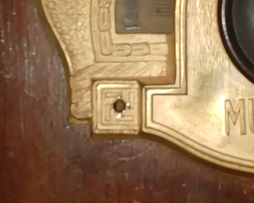
One oddity is the pair of swastikas gracing the lower faceplate screw holes.
Wikipedia reports that
the motif was common in Native American design and was in general use as a symbol of the
sun, of life, and of good luck. This radio's date of manufacture is probably close to
the tipping point past which a swastika would have carried a darker meaning for North
Americans.
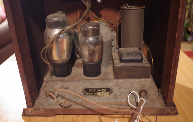
The radio arrived in the condition shown below. The stray wires turned out to be for the antenna and probably the ground. Everything was predictably dirty. The seller had said that the tubes lit up but no sound came out, and I didn't test this until I had re-capped it.
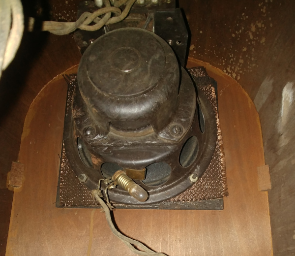
The speaker has a massive chunk of iron in back housing the field coil. Up front, it has been re-coned. In this picture you can see the positioning of the pilot light, which doesn't light up the dial particularly well. The grill cloth appears to be original, and is very fragile.
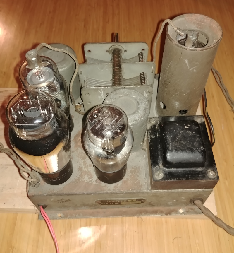
Next are three views of the chassis top with it out of the cabinet. These were taken after the restoration so the dust is gone and the tubes are shined up. Going approximately clockwise from the upper left, and following the part numbering I provide later on, the components are:
-
T1 – Power transformer
-
L2 – RF transformer
-
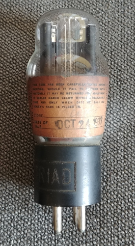
V4 – 80 diode fullwave rectifier
-
V3 – 47 pentode audio amplifier
-
V2 – 24A tetrode RF amplifier/detector (?)
-
L1 – RF transformer
-
C1 – Tuning capacitor
-
Disconnected can for original electrolytic capacitors
-
V1 – 24A tetrode RF amplifier, shielded
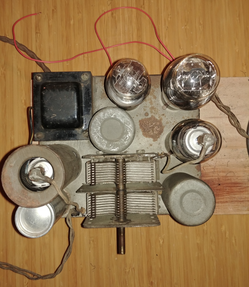
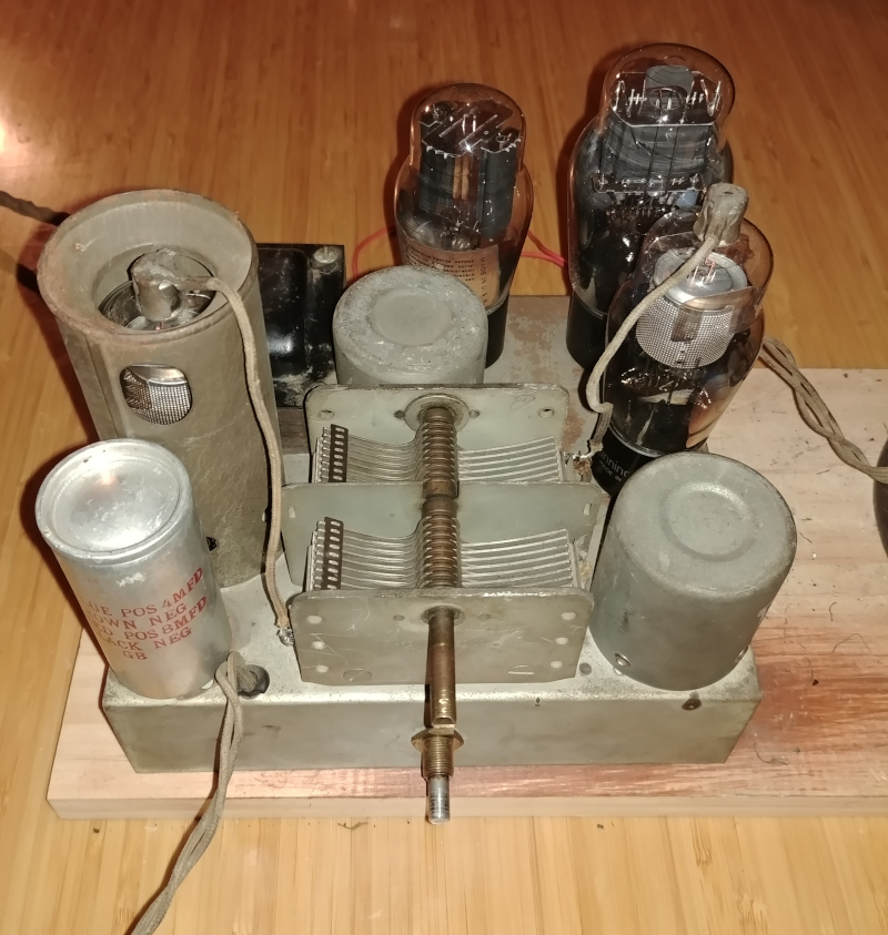
The diode has a label with a date: October 24, 1933. So that's that as earliest possible manufacturing date.
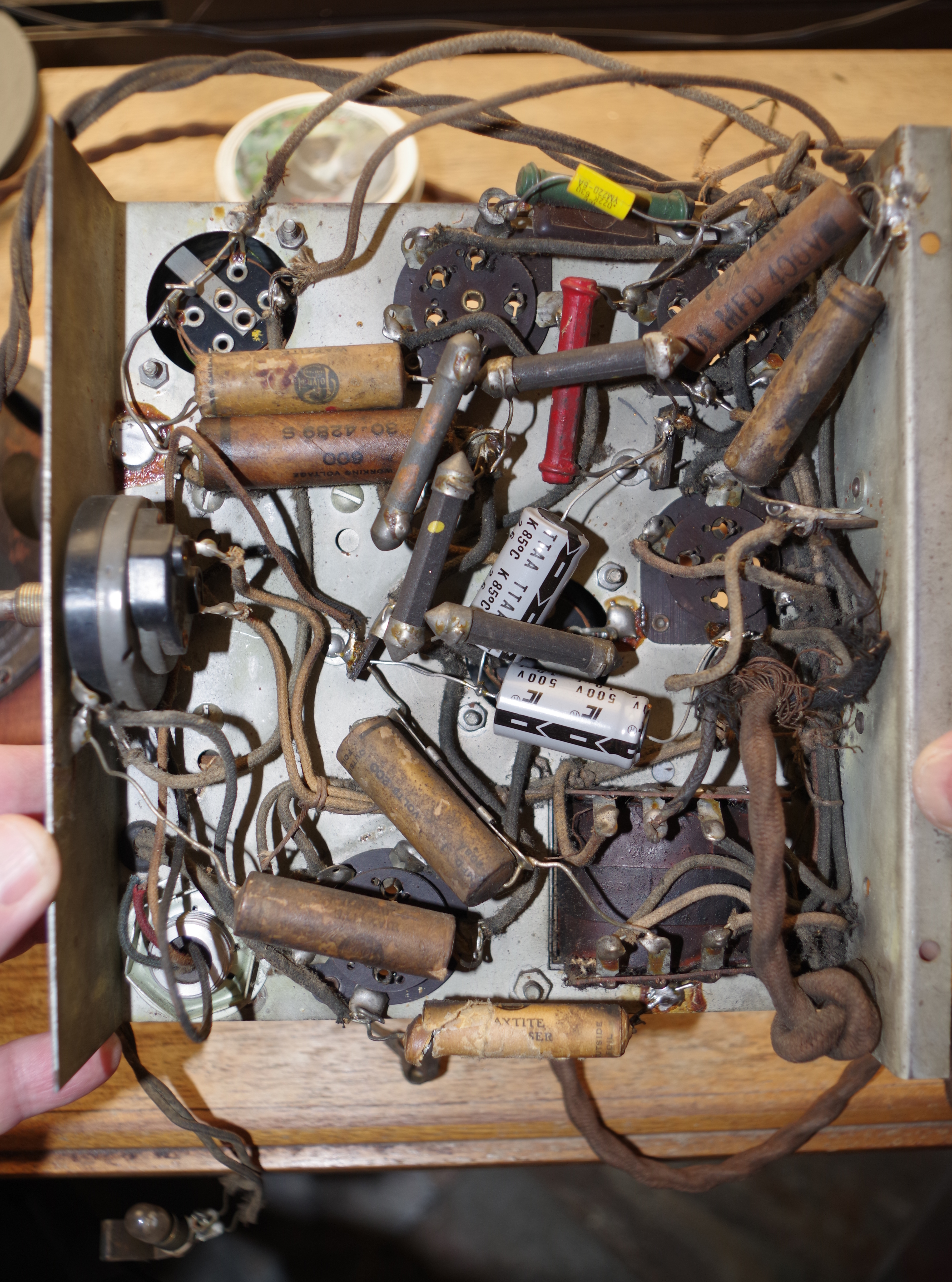
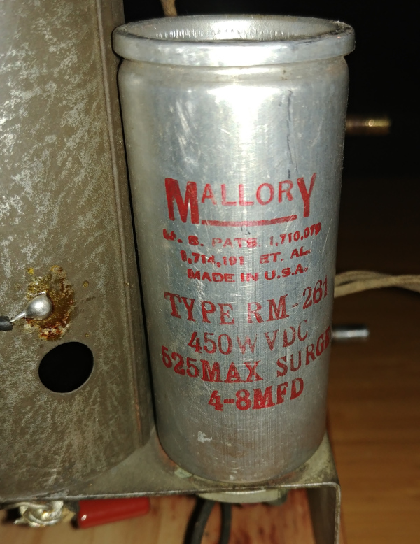
Now the fun part. This is the underside of the chassis prior to restoration. Somebody had been there before me. One tiny-value capacitor had been replaced as well as the two electrolytics. At lower left, you can see the clipped red and green wires that lead into the old electrolytic capacitor can. There is also a clearly non-functional paper capacitor at the bottom. I was very pleased by the highly retro dogbone resistors everywhere.
The single most puzzling component was the large paper capacitor (C12) just below the middle. It has a ferrite-cored coil (L3) wired in parallel alongside it. When I snipped off the old capacitor, I broke the ferrite and the coil unfurled itself like a deranged Slinky. I managed to collect the extremely fine wire back into an almost-helix, shoved the ferrite chunks back together, and wrapped it all in electrical tape. I managed not to break the wire. I have no idea what is so special about this (filter?) capacitor that it is entitled to this kind of coil.
I took care not to disturb the wiring harnesses with vintage cable-lacing below the middle and on the right. In general, the old cloth-wrapped wiring was still usable.
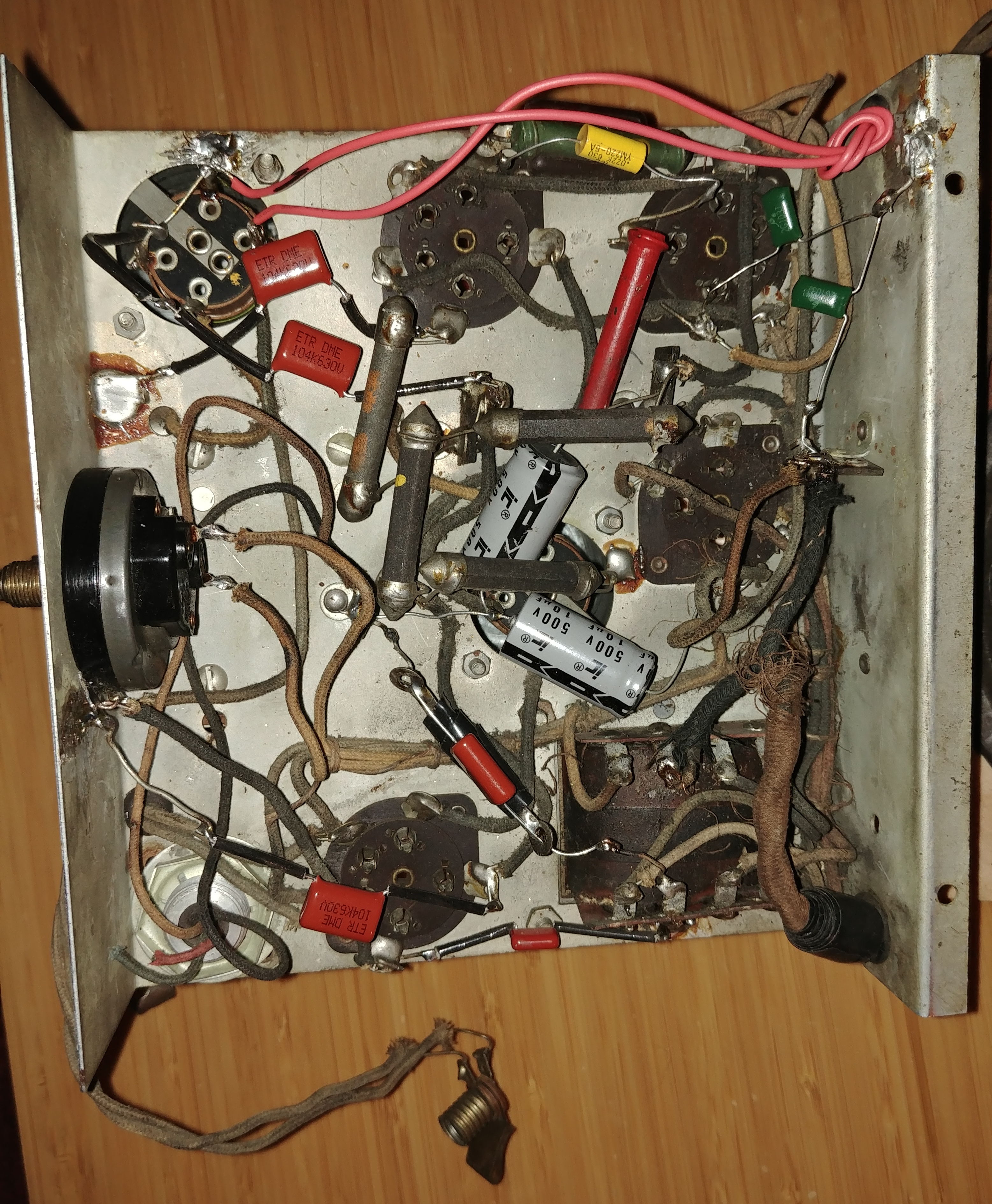
And here is the final product, with a lot less clutter. I kept the old power
cord but had to clip a few inches of it. The cloth wrapping was too delicate to tie in a
new knot, so I stopped it from pulling through the access port with a bunch of
electrical tape. Not very pretty.
Here is a memorial to the abandoned electrolytic capacitor can.
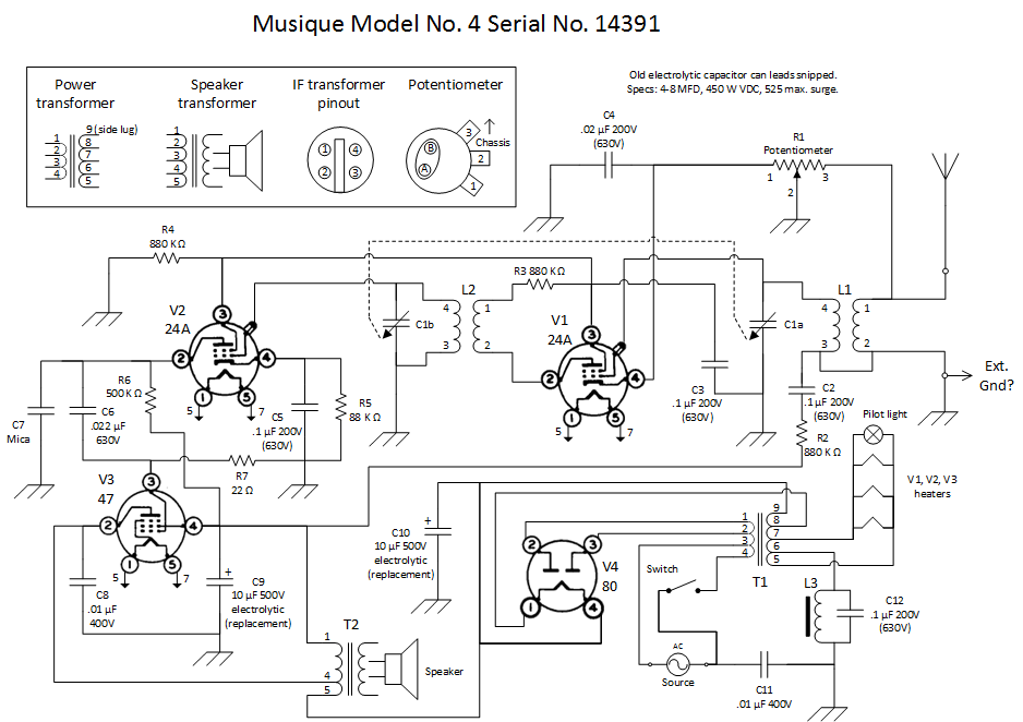
This is my first attenpt at drawing a schematic entirely from inspection and testing. There are probably mistakes that someone with a little more electronics knowledge would easily spot. I used Visio, the only Microsoft product I respect.
I rebuilt and tested the potentiometer. I took it apart because the volume on the restored radio was too loud. This failed to solve that problem – it's still too loud. The only way to cut the volume significantly is to attach a shorter antenna.
Having messed with a few other old radios, I was surprised to find that the Musique's heaters (and pilot light) are wired in parallel. This seems a lot more sensible than wiring them in series like antique Christmas lights. On the other hand, maybe it makes no difference, since a single dead tube would kill performance as effectively as all of them going dark. But at least this way the radio still works if the pilot light burns out.
As a convention in this schematic, I state the original capacitor specs, and then provide specs of replacement components in parentheses where they differ.
The speaker and its various transformer and coil internals are a mystery to me, presented here as a black box except for the three inputs to the transformer primary.
-
V1 24A tetrode
-
V2 24A tetrode
-
V3 47 pentode
-
V4 80 diode
-
L1 RF transformer
-
L2 RF transformer
-
L3 Mystery ferrite-core coil
-
T1 Power transformer
-
T2 Speaker transformer (integrated with speaker)
-
C1 2-gang variable capacitor
-
C2 .1 µF 200V paper capacitor (replaced by 630V ceramic)
-
C3 .1 µF 200V paper capacitor (replaced by 630V ceramic)
-
C4 .02 µF 200V paper capacitor (replaced by 630V ceramic)
-
C5 .1 µF 200V paper capacitor (replaced by 630V ceramic)
-
C6 .022 µF 630V (not original)
-
C7 Mica capacitor
-
C8 .01 µF 400V paper capacitor (replaced by polyester)
-
C9 10 µF 500V electrolytic (replaces original in can)
-
C10 10 µF 500V electrolytic (replaces original in can)
-
C11 .01 µF 400V paper capacitor (replaced by polyester)
-
C12 .1 µF 200V paper capacitor (replaced by 630V ceramic)
-
R1 Potentiometer (integrated with switch)
-
R2 880 K Ω
-
R3 880 K Ω
-
R4 880 K Ω
-
R5 88 K Ω
-
R6 500 K Ω
-
R7 22 Ω
-
Switch (power, integrated with potentiometer)
-
Speaker (integrated with transformer T2)